COURSES
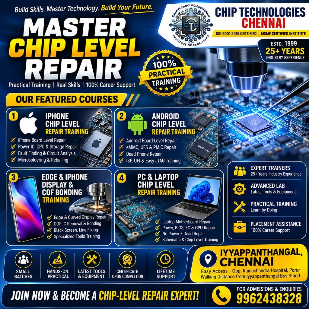
Comprehensive Training for ANDROID MASTER CHIP LEVEL – IPHONE MASTER CHIP LEVEL – EDGE & CURVED DISPLAY REPAIR , LINE REMOVAL COF BONDING TRAINING & PC & Laptop CHIP LEVEL SERVICE TRAINING
ANDROID MASTER CHIP LEVEL SERVICE TRAINING
DURATION : 60 HOURS
FEES : 19,999/-
SYLLABUS:
ANDROID MASTER CHIP-LEVEL REPAIR TRAINING ( ANDROID SMARTPHONE BASIC LEVEL FREE!!! )
UPDATED SYLLABUS
60 Hours 30 Days 2 Hours Daily
Level: Advanced → Master Mode: Theory + Live Board Practical Focus: Android Motherboard / Micro-Level / Chip-Level /
Dead Phone Repair
MODULE 1 — ADVANCED ELECTRONICS & MOTHERBOARD BASICS
Days 1–3 | 6 Hours
Day 1 — Mobile Electronics Fundamentals
Voltage, current, resistance and power
AC vs DC
Open circuit & short circuit
Ground concepts
Positive/negative lines
Series & parallel circuits
Resistor, capacitor, coil and diode
Transistor & MOSFET basics
Understanding SMD components
Component identification on Android motherboard
Day 2 — Multimeter Mastery
Digital multimeter functions
Continuity mode
Diode mode
Resistance measurement
Voltage measurement
Current measurement
Capacitor testing
Coil testing
Diode testing
MOSFET testing
Finding open tracks
Finding short circuits
Ground vs non-ground line identification
Practical board testing
Day 3 — Android Motherboard Architecture
Motherboard layer identification
PCB sections
Power section
Charging section
CPU section
RAM section
eMMC/eMCP section
UFS section
RF/network section
Audio section
Display/touch section
Camera section
USB section
Clock/reset sections
Block diagram understanding
Live motherboard tracing
MODULE 2 — SCHEMATIC & BOARDVIEW TRAINING
Days 4–5 | 4 Hours
Day 4 — Schematic Reading
How to read Android schematics
Component reference numbers
Net names
Power rails
Coil-to-IC tracing
Capacitor network tracing
Test points
Ground points
Input/output identification
Finding IC pin connections
Voltage line tracing
Day 5 — Boardview / PCB Layout
Boardview fundamentals
Finding components
Finding missing components
Track tracing
Via identification
Layer identification
Net search
Finding test points
Schematic ↔ PCB correlation
Live tracing practice
Recommended practice: Use boardview/schematic software and real donor Android boards.
MODULE 3 — SOLDERING, SMD & MICRO-LEVEL WORK
Days 6–8 | 6 Hours
Day 6 — Professional Soldering
Soldering station setup
Temperature selection
Flux selection
Solder wire selection
Tip selection
Pad preparation
Component removal
Component replacement
Solder bridge removal
Solder wick technique
Microscope work
Day 7 — SMD Components
Resistor replacement
Capacitor replacement
Coil replacement
Diode replacement
Transistor/MOSFET replacement
IC replacement basics
Jumper techniques
Track repair
Pad repair
Via repair
Day 8 — Hot Air & Rework
Hot-air machine settings
Airflow control
Preheating
IC removal
IC placement
Solder-ball preparation
Flux application
Avoiding PCB damage
Nearby-component protection
Practical IC removal/refitting
MODULE 4 — SHORT-CIRCUIT FINDING MASTER CLASS
Days 9–10 | 4 Hours
Day 9 — Short Finding Techniques
Short-to-ground concept
Resistance method
Diode-mode method
DC power-supply method
Current-consumption observation
Thermal detection
Rosin/IPA method
Capacitor short identification
Coil short analysis
Day 10 — Advanced Short Diagnosis
Main power rail shorts
Secondary rail shorts
PMIC-related shorts
Charging-line shorts
USB/VBUS shorts
CPU-area shorts
RF-area shorts
Thermal camera/short finder workflow
Safe voltage injection principles
Live short-board practical
MODULE 5 — POWER MANAGEMENT / PMIC
Days 11–12 | 4 Hours
Day 11 — Power Section
Battery line
VBAT
VPH_PWR
Main power rails
Power key circuit
RTC circuit
PMIC basics
Buck/boost/LDO concepts
Enable signals
Power sequencing
Day 12 — PMIC Troubleshooting
No power diagnosis
High current diagnosis
Low current diagnosis
Dead motherboard testing
Missing power rail
PMIC input/output testing
PMIC surrounding components
PMIC replacement
PMIC reballing
Live dead-board practical
MODULE 6 — CHARGING & USB SECTION
Day 13 | 2 Hours
USB connector
VBUS
D+ / D−
USB-C fundamentals
Charging IC
Charging coil
Protection components
ESD components
CC lines
No charging
Slow charging
Charging but battery percentage not increasing
USB detection problems
PC connection problems
Charging IC diagnosis
Charging section practical
MODULE 7 — CPU / RAM / AP PROCESSOR LEVEL
Days 14–16 | 6 Hours
Day 14 — CPU Architecture
Application processor concept
CPU power supplies
CPU clocks
Reset signals
CPU communication
CPU surrounding components
CPU-related dead phone diagnosis
CPU vs PMIC fault differentiation
Day 15 — CPU Reballing
CPU removal preparation
Board heating
Shield/component protection
CPU lifting
Cleaning CPU pads
Stencil selection
Ball size selection
Reballing procedure
CPU refitting
Post-repair testing
Day 16 — CPU-Level Fault Diagnosis
CPU solder-joint problems
CPU power problems
CPU boot problems
CPU communication problems
Boot-loop diagnosis
Dead CPU-area diagnosis
CPU rework precautions
Advanced live-board practical
Important: CPU drilling and destructive techniques should only be taught as controlled advanced-boardwork, after the student
understands board construction and data-preservation risks.
MODULE 8 — eMMC / eMCP MASTER TRAINING
Days 17–19 | 6 Hours
Day 17 — eMMC Fundamentals
eMMC architecture
eMMC vs eMCP
BGA packages
eMMC pin identification
CMD
CLK
DAT0–DAT7
VCC
VCCQ
GND
Reset
Datasheet reading
Day 18 — eMMC Programming
eMMC identification
Health checking
Read/write concepts
CID
CSD
EXT_CSD
User area
Boot partition
RPMB concept
Dump handling
Backup procedures
eMMC programming using professional programmers
Day 19 — eMMC Faults
eMMC not detected
Boot hang
Logo stuck
Dead phone due to memory
Corrupt partition
Bad health
eMMC replacement
Reballing
Programming
Board-level verification
MODULE 9 — UFS MASTER TRAINING
Days 20–21 | 4 Hours
Day 20 — UFS Technology
UFS vs eMMC
UFS architecture
UFS power supplies
UFS communication
TX/RX concept
UFS package identification
UFS pinout/datasheet
Common UFS faults
Day 21 — UFS Programming
UFS identification
Health checking
Reading information
Backup concepts
Programming
UFI/JTAG-compatible workflows
UFS replacement
Reballing
Boot-related troubleshooting
Live UFS board practical
ADDED MASTER TRAINING — F64 BOX PROGRAMMING
Integrated into eMMC & UFS Programming Practical
F64 Box introduction and professional workflow
F64 Box hardware and software overview
Android memory-device connection and detection
eMMC identification, read, backup, write and programming workflow
UFS identification, read, backup, write and programming workflow
Dump handling, verification and troubleshooting
Practical F64 Box programming on suitable service/donor boards
ADDED MASTER TRAINING — THERMAL CAMERA & SHORT KILLER
Integrated into Short-Circuit Finding Master Class
Thermal camera setup and operation
Thermal image interpretation and abnormal heat detection
Locating shorted components and power-rail shorts
Short Killer introduction and safe operating procedure
Controlled voltage/current injection principles
Capacitor, coil and main/secondary rail short diagnosis
Thermal Camera + Short Killer combined short-finding workflow
Board protection and safe injection practices
Live short-board practical
MODULE 10 — NETWORK / RF SECTION
Days 22–23 | 4 Hours
Day 22 — Network Circuit
SIM section
SIM power
SIM detection
RF power supply
Network IC
RF IC
PA
Antenna switch
Filters
Coils
Network signal tracing
Day 23 — Network Fault Finding
No SIM
SIM not detected
Emergency calls only
No service
Weak signal
4G/5G network problems
RF line testing
PA diagnosis
Network IC diagnosis
Practical board tracing
MODULE 11 — AUDIO / DISPLAY / CAMERA / SENSOR IC
Day 24 | 2 Hours
Audio codec
Speaker circuit
Mic circuit
Receiver circuit
Audio amplifier
Display power
Display data lines
Touch section
Backlight/display supply
Camera power
Camera communication
Fingerprint section
Sensors
Practical troubleshooting
MODULE 12 — ANDROID SOFTWARE + HARDWARE CORRELATION
Days 25–26 | 4 Hours
Day 25 — Android Software Diagnosis
Boot modes
Recovery
Fastboot
Download mode
EDL concept
Firmware structure
Flashing fundamentals
Firmware selection
Boot-loop diagnosis
Software vs hardware fault identification
Day 26 — Professional Programming
USB tester
Flashing tools
EDL tools
UFI
JTAG concepts
Dump read/write
Firmware extraction
Partition concepts
Error-code interpretation
Hardware/software correlation
MODULE 13 — DEAD PHONE MASTER REPAIR
Days 27–28 | 4 Hours
Day 27 — Dead Phone Diagnosis
Completely dead phone
No current
Low current
High current
Current stuck
Power key not responding
PMIC diagnosis
CPU diagnosis
eMMC/UFS diagnosis
Missing voltage diagnosis
Short-circuit diagnosis
Day 28 — Advanced Dead Board Practical
Students receive faulty motherboards and perform:
Complaint → Visual inspection → Diode test → Resistance → Power injection → Voltage tracing → Schematic tracing → IC
isolation → IC replacement → Software test → Final diagnosis
This is particularly important because the goal is to teach diagnostic thinking, not simply memorizing common faults.
MODULE 14 — MASTER CASE STUDIES
Days 29–30 | 4 Hours
Day 29 — Live Fault Case Studies
Practice multiple real Android boards:
Dead phone
No charging
Auto restart
Boot loop
No display
No touch
No network
SIM not detected
Battery drain
Overheating
USB not detected
eMMC/UFS problem
Day 30 — FINAL MASTER PRACTICAL
Each student must independently perform:
Motherboard identification
Schematic tracing
Component identification
Multimeter diagnosis
Short finding
DC power-supply analysis
Voltage tracing
SMD replacement
IC removal
IC reballing
IC refitting
eMMC/UFS diagnosis
Software/hardware correlation
Final repair verification
■■ TOOLS & MACHINES TO COVER
The training should include hands-on operation of:
Professional microscope
Soldering station
Hot-air rework station
DC power supply
Digital multimeter
Oscilloscope/DSO
Thermal camera/thermal detector
Short-finding equipment
PCB preheater
BGA/reballing equipment
SMD tools
Flux and soldering materials
USB tester
eMMC programmer
UFS programmer
UFI-type programmer
JTAG-related equipment
Android flashing tools
Boardview/schematic software
Professional micro/chip-level repair tools
■ 60-HOUR COURSE STRUCTURE
Daily timing
2 hours × 30 days = 60 hours
IPHONE MASTER CHIP LEVEL SERVICE TRAINING
DURATION : 60 HOURS
FEES : 29,999/-
SYLLABUS:
iPHONE MASTER CHIP-LEVEL REPAIR TRAINING ( IPHONE BASIC LEVEL FREE !!!)
60 HOURS • 30 DAYS • 2 HOURS DAILY
Models Covered: iPhone 7 iPhone X iPhone 11 iPhone 12 iPhone 13 iPhone 14 Level: Advanced → Master
Method: Theory + Schematic + Boardview + Live Motherboard Practical
MODULE 1 — iPHONE ELECTRONICS & BOARD ARCHITECTURE
Days 1–3 | 6 Hours
Day 1 — iPhone Electronics Fundamentals
Voltage, current, resistance
DC power concepts
Ground and power rails
SMD components
Resistors
Capacitors
Coils
Diodes
Filters
MOSFETs
Transistors
IC identification
iPhone motherboard component identification
Single-layer vs sandwich motherboard concept
Day 2 — Multimeter Mastery
Continuity mode
Diode mode
Resistance mode
Voltage measurement
Current measurement
Finding short to ground
Finding open lines
Checking capacitors
Checking coils
Checking diodes
Comparing good vs faulty board readings
Creating diode-mode reference measurements
Day 3 — iPhone Motherboard Architecture
Detailed study of:
iPhone 7
Power section
Audio section
Charging section
Baseband/network
Display/touch
Camera
NAND/CPU/RAM
iPhone X
Dual-layer/sandwich board concept
CPU/RAM/NAND
PMIC
Face ID
Baseband
Charging
Display
iPhone 11/12/13/14
Logic-board architecture
Power management
NAND
CPU
Baseband
Charging
Display
Camera
Face ID
Wireless charging
Important communication buses
MODULE 2 — SCHEMATIC & BOARDVIEW
Days 4–5 | 4 Hours
Day 4 — iPhone Schematic Reading
Schematic symbols
Reference designators
Net names
Power rails
PP_VDD_MAIN
PP_BATT_VCC
PP_VDD_CPU
PP1V8
PP3V0
Enable signals
Communication lines
IC pin tracing
Component-to-IC tracing
Power-sequence understanding
Day 5 — Boardview Training
Finding components
Finding test points
Finding missing components
Layer identification
Via tracing
Inner-layer tracing
Schematic ↔ boardview correlation
Finding alternative test points
Lost-track diagnosis
Live board tracing
MODULE 3 — MICRO-SOLDERING & iPHONE REWORK
Days 6–8 | 6 Hours
Day 6 — Micro-Soldering
Microscope operation
Soldering iron control
Flux selection
Micro-tip selection
Solder bridge removal
Jumper wire techniques
Pad cleaning
FPC connector work
Small component replacement
Day 7 — SMD Component Repair
Capacitor replacement
Resistor replacement
Coil replacement
Diode replacement
Filter replacement
MOSFET replacement
Missing component installation
Pad repair
Track repair
Via repair
Day 8 — IC Rework
Hot-air settings
Preheater operation
Shield protection
IC removal
IC cleaning
PCB pad preparation
Stencil selection
BGA reballing
IC refitting
Microscope inspection
Post-repair testing
MODULE 4 — iPHONE SHORT-CIRCUIT MASTER
Days 9–10 | 4 Hours
Day 9 — Short Finding
Short-to-ground concept
Diode-mode short detection
Resistance testing
DC power-supply method
Current consumption analysis
Thermal detection
IPA/rosin method
Capacitor short
Coil short
Main-rail short
Day 10 — Advanced Short Diagnosis
Practical faults from:
iPhone 7
iPhone X
iPhone 11
iPhone 12
iPhone 13
iPhone 14
Training on:
PP_VDD_MAIN shorts
Secondary power-rail shorts
Charging-related shorts
Display-related shorts
Camera-related shorts
RF-related shorts
PMIC-related shorts
Safe voltage injection
Thermal camera workflow
MODULE 5 — POWER MANAGEMENT / PMIC
Days 11–12 | 4 Hours
Day 11 — iPhone Power Architecture
Battery connector
Battery communication
Main power rail
PMIC
Buck converters
Boost converters
LDOs
Power enable
Power sequencing
Power key circuit
RTC/clock circuits
Day 12 — No Power Diagnosis
Completely dead iPhone
No current
Low current
High current
Current stuck
Boot-current analysis
Missing voltage
PMIC diagnosis
PMIC surrounding components
PMIC replacement
PMIC reballing
Live dead-board practical
MODULE 6 — CHARGING / USB / LIGHTNING / USB-C
Day 13 | 2 Hours
iPhone 7 / X / 11
Lightning connector
VBUS
USB communication
Charging IC
USB protection
Charging coil
ESD components
Charging-line tracing
iPhone 12 / 13 / 14
Lightning/USB-C architecture as applicable to the model
Charging circuit
USB communication
Charging protection
Wireless charging interaction
Charging fault diagnosis
Practical Problems
No charging
Slow charging
Charging intermittently
USB not detected
Computer not detecting phone
Charging IC faults
Connector-line faults
MODULE 7 — CPU / RAM / NAND CHIP-LEVEL
Days 14–16 | 6 Hours
Day 14 — CPU Architecture
Apple SoC concept
CPU power rails
CPU clocks
Reset
Communication lines
CPU surrounding circuitry
CPU-related dead-phone diagnosis
Day 15 — NAND / Storage
NAND architecture
NAND power supply
NAND communication
NAND replacement concept
NAND reballing
NAND programming
Storage-related boot problems
Data-preservation considerations
Day 16 — CPU / RAM Rework
CPU area inspection
Underfill concept
Controlled heating
IC removal precautions
Pad cleaning
BGA reballing
IC refitting
Post-repair inspection
Fault diagnosis
Models for practical: iPhone 7, X, 11, 12, 13 and 14.
MODULE 8 — AUDIO IC & AUDIO CIRCUIT
Day 17 | 2 Hours
iPhone 7
Audio IC section
Common audio faults
Audio lines
Mic/speaker circuits
IC diagnosis
iPhone X / 11 / 12 / 13 / 14
Audio codec
Amplifier
Speaker
Receiver
Microphone
Audio power rails
Audio communication lines
Practical
No speaker
No microphone
Voice recording problem
Call audio problem
Speaker distortion
Audio IC diagnosis
MODULE 9 — BASEBAND / NETWORK / RF
Days 18–19 | 4 Hours
Day 18 — Baseband Architecture
Baseband CPU
Baseband PMIC
RF transceiver
Power amplifier
Antenna switch
RF filters
Coils
RF power supplies
Clock circuits
Network communication
Day 19 — Network Fault Diagnosis
No service
Searching
Emergency calls only
IMEI-related diagnostic concepts
Modem/baseband faults
SIM detection
Weak signal
4G/5G problems
RF line tracing
Baseband power diagnosis
Live board practical
MODULE 10 — FACE ID / TOUCH ID / BIOMETRIC
Day 20 | 2 Hours
iPhone 7
Touch ID architecture
Home-button communication
Button replacement considerations
Touch ID pairing concept
iPhone X
Face ID architecture
Dot projector
Flood illuminator
IR camera
Face ID communication
Common Face ID faults
iPhone 11–14
Face ID system
Sensor communication
Flood illuminator
Dot projector
Proximity/ambient sensor
Flex-related faults
Practical
Face ID not working
Sensor line diagnosis
Connector/flex faults
Microsoldering around biometric circuits
MODULE 11 — DISPLAY / TOUCH / BACKLIGHT
Day 21 | 2 Hours
Display connector
Display power
Touch communication
Backlight circuit
Display filters
Display-related power rails
Touch IC
OLED/LCD architecture
Display FPC repair
Connector damage
Missing component diagnosis
Faults
No display
White screen
Green/colored display
Touch not working
Partial touch
Display flickering
Backlight problem
Display connector damage
MODULE 12 — CAMERA / SENSOR / PERIPHERAL CIRCUITS
Day 22 | 2 Hours
Front camera
Rear camera
OIS
Camera power
Camera communication
Proximity sensor
Ambient light sensor
Gyroscope
Accelerometer
Compass
Flash
Camera connector
Sensor power rails
Communication-line tracing
Practical faults
Camera not opening
Black camera
Flash not working
Front camera fault
Proximity sensor problem
Sensor malfunction
MODULE 13 — WIRELESS CHARGING / NFC / CONNECTIVITY
Day 23 | 2 Hours
Wireless charging architecture
Charging coil
Charging controller
NFC circuit
NFC antenna
Wireless power communication
Wi-Fi section
Bluetooth section
Related power rails
Communication lines
Short diagnosis
Practical
Wireless charging failure
NFC failure
Wi-Fi problem
Bluetooth problem
Component-level diagnosis
MODULE 14 — iOS SOFTWARE + HARDWARE CORRELATION
Days 24–25 | 4 Hours
Day 24 — iOS Diagnostics
Recovery mode
DFU mode
Restore process
Update vs restore
Error-code interpretation
Boot-loop diagnosis
Panic-log concept
Hardware vs software diagnosis
Firmware troubleshooting
Day 25 — Advanced Diagnostic Workflow
3uTools-type diagnostic workflow
Apple restore tools
DFU testing
Panic analysis
Restart/boot-loop analysis
NAND-related symptoms
Baseband-related symptoms
Sensor-related panic symptoms
Hardware/software correlation
MODULE 15 — SANDWICH BOARD / LAYER SEPARATION
Days 26–27 | 4 Hours
Day 26 — Sandwich Board Technology
Particularly:
iPhone X / XS-generation style board construction and later stacked-board concepts
Upper/lower board concept
Interposer
Sandwich construction
Board separation
Heating control
Underfill
Layer cleaning
Interposer inspection
Pad inspection
Day 27 — Sandwich Board Repair
Board separation
Reballing
Interposer work
Layer alignment
Rejoining
Continuity testing
Short testing
Power testing
Boot testing
This module should emphasize controlled temperature and board protection, because excessive heat can permanently
damage multilayer boards.
MODULE 16 — DEAD iPHONE MASTER REPAIR
Days 28–29 | 4 Hours
Day 28 — Dead iPhone Diagnosis
Students diagnose:
No power
No current
High current
Low current
Boot-loop
Apple-logo stuck
Recovery-loop
Restarting
No charging
No display
No network
Using:
Visual inspection → diode mode → resistance → DC supply → current analysis → schematic → boardview → voltage
tracing → signal tracing → component/IC diagnosis
Day 29 — Live Dead-Board Repairs
Practical boards:
iPhone 7
iPhone X
iPhone 11
iPhone 12
iPhone 13
iPhone 14
Students independently diagnose and repair selected faulty boards.
MODULE 17 — MASTER PRACTICAL & CASE STUDIES
Day 30 | 2 Hours
FINAL MASTER TEST
Each student receives a faulty iPhone motherboard.
Student must perform:
Complaint analysis
Visual inspection
Motherboard identification
Schematic search
Boardview search
Diode measurement
Resistance measurement
Short detection
DC power-supply testing
Voltage tracing
Signal tracing
Component identification
SMD replacement
Micro-jumper
IC diagnosis
IC removal/reballing where appropriate
Software testing
Final repair verification
📱 ADVANCED FLAT DISPLAY + EDGE CURVED DISPLAY + COF BONDING TRAINING
DURATION : 10 DAYS 3 hours Daily Total 30 Hours
FEES :14999/=
SYLLABUS:
🔵 DAY 1 — DISPLAY TECHNOLOGY & BASIC ELECTRONICS
3 Hours
Theory
- LCD vs OLED vs AMOLED
- Flat display vs curved/edge display
- Display layers and construction
- Glass, polarizer, OCA, TFT and OLED layers
- Display FPC structure
- Display IC / Driver IC
- COF concept
- TAB/COF/FPC differences
- VCC, VDD, VGH, VGL and common display supply concepts
- Display communication basics
Practical
- Identify different damaged displays
- Identify FPC, COF and display IC
- Microscope inspection
🔵 DAY 2 — DISPLAY DISASSEMBLY & GLASS SEPARATION
3 Hours
- Display frame separation
- LCD/OLED assembly construction
- Removing damaged glass
- OCA identification
- Display heating techniques
- Temperature control
- Wire/film separation techniques
- Avoiding TFT/OLED damage
- Cleaning old OCA
- Glass preparation
- Practical display separation
Practical:
Flat LCD/OLED live display separation
🔵 DAY 3 — OCA REMOVAL & DISPLAY CLEANING
3 Hours
- OCA structure
- OCA removal techniques
- Manual OCA removal
- OCA cleaning
- Glue/adhesive removal
- Glass cleaning
- Bubble prevention
- Dust prevention
- Polarizer protection
- Display inspection under microscope
- Common mistakes during cleaning
Practical:
Complete OCA removal + display cleaning
🔵 DAY 4 — OCA LAMINATION & FLAT DISPLAY REFURBISHING
3 Hours
- OCA film selection
- OCA cutting
- Alignment techniques
- Laminator operation
- Vacuum lamination
- Bubble removal
- Autoclave/bubble-removal machine operation
- Pressure and temperature concepts
- Flat display glass alignment
- Final inspection
Practical:
Complete flat display OCA lamination
🔵 DAY 5 — FLAT DISPLAY TESTING & REPAIR
3 Hours
Fault Diagnosis
- No display
- White display
- Lines
- Flickering
- Touch problems
- Partial display
- Dead pixels
- Display connector damage
- FPC damage
- Display IC-related symptoms
Practical
- Display testing
- FPC inspection
- Continuity testing
- Diode/resistance testing where appropriate
- Display quality inspection
- Refurbished display testing
🔴 DAY 6 — EDGE CURVED DISPLAY TECHNOLOGY
3 Hours
Advanced Theory
- Flat vs edge-curved OLED
- Curved OLED construction
- Flexible OLED structure
- Curved glass
- Flexible FPC
- COF/driver section
- COF bonding concept
- Display bonding area
- Why curved displays are difficult to refurbish
- Heating and pressure control
Practical
- Identify curved display layers
- Identify COF bonding area
- Microscope inspection
- Damage analysis
🔴 DAY 7 — COF BONDING FUNDAMENTALS
3 Hours
- What is COF?
- COF film construction
- ACF concept
- COF-to-glass bonding
- COF-to-FPC bonding
- Bonding machine introduction
- Alignment microscope
- Temperature control
- Pressure control
- Bonding time
- Proper alignment
- Removing defective COF
- Cleaning bonding area
Practical:
COF removal and bonding-machine setup practice
🔴 DAY 8 — EDGE CURVED DISPLAY COF BONDING
3 Hours
Advanced Practical
- Curved display positioning
- COF alignment
- ACF placement
- Pre-bonding preparation
- Main bonding procedure
- Temperature/pressure/time control
- Avoiding COF wrinkles
- Avoiding glass damage
- Preventing bonding-line defects
- Bond inspection
- Electrical testing after bonding
Practical:
Live edge-curved display COF bonding
🔴 DAY 9 — ADVANCED COF FAULT FINDING & REWORK
3 Hours
Faults
- Vertical lines
- Horizontal lines
- Partial display
- Half display
- Flickering
- Missing rows/columns
- No display
- Touch/display combination faults
- COF open
- Poor bonding
- ACF bonding failure
- Misalignment
Practical
- Bond inspection
- Re-bonding
- Faulty COF diagnosis
- Alignment correction
- Bonding pressure/temperature adjustment
- Before/after testing
🟢 DAY 10 — MASTER PRACTICAL & FINAL DISPLAY REFURBISHING
3 Hours
Each student performs a complete display refurbishment workflow.
Flat Display Practical
Display testing → separation → OCA removal → cleaning → OCA lamination → bubble removal → final testing
Edge Curved Display Practical
Testing → separation/preparation → COF inspection → COF alignment → ACF preparation → bonding → inspection → final testing
💻 PC & LAPTOP MASTER CHIP-LEVEL REPAIR TRAINING
DURATION 60 HOURS
FEES : 14,999/-
SYLLABUS:
PC & LAPTOP ADVANCED CHIP-LEVEL REPAIR TRAINING ( BASIC CARD LEVEL FREE !!!)
60 HOURS • 30 DAYS • 2 HOURS DAILY
Level: Advanced → Master
Coverage: Desktop PC + Laptop Motherboards
Method: Theory + Schematic + Boardview + Live Faulty Board Practical
MODULE 1 — ADVANCED ELECTRONICS
Days 1–3 | 6 Hours
Day 1 — Electronics Fundamentals
• Voltage, current, resistance and power
• Ohm’s Law
• AC vs DC
• Open and short circuits
• Series and parallel circuits
• Ground concepts
• Resistors
• Capacitors
• Coils/inductors
• Diodes
• Zener diodes
• Transistors
• MOSFETs
• IC identification
• SMD component identification
• Component testing
Day 2 — Multimeter Mastery
• Continuity mode
• Diode mode
• Resistance measurement
• Voltage measurement
• Current measurement
• Capacitor testing
• Coil testing
• Diode testing
• MOSFET testing
• Short-to-ground testing
• Open-track identification
• Comparing good vs faulty boards
Day 3 — PCB & Motherboard Architecture
• PCB layers
• Ground plane
• Power plane
• Signal layers
• Vias
• Test points
• Connectors
• Motherboard block diagram
• Desktop vs laptop motherboard
• Major motherboard sections
MODULE 2 — SCHEMATIC & BOARDVIEW MASTER
Days 4–5 | 4 Hours
Day 4 — Schematic Reading
• Understanding schematic symbols
• Component reference designators
• Net names
• Power rails
• Ground symbols
• IC pin numbers
• Page-to-page connections
• Block diagrams
• Datasheet reference
• Voltage tracing
• Signal tracing
• Power sequence tracing
Day 5 — Boardview
• Boardview software
• Component location
• Net search
• Power rail search
• Ground search
• Finding missing components
• Finding alternative test points
• Schematic ↔ boardview correlation
• IC → component → rail tracing
• Lost-track diagnosis
Schematic and boardview are particularly important because the schematic explains the circuit while boardview helps locate the physical component and net on the motherboard.
MODULE 3 — SOLDERING & SMD REWORK
Days 6–8 | 6 Hours
Day 6 — Soldering
• Soldering station
• Tip selection
• Flux
• Solder wire
• Solder paste
• Solder wick
• SMD soldering
• Through-hole soldering
• Pad cleaning
• Component replacement
Day 7 — SMD Component Repair
• Resistor replacement
• Capacitor replacement
• Coil replacement
• Diode replacement
• MOSFET replacement
• Transistor replacement
• Fuse replacement
• Jumper wire
• Track repair
• Pad repair
• Via repair
Day 8 — IC Rework
• Hot-air station
• Preheater
• Temperature control
• IC removal
• PCB pad cleaning
• BGA preparation
• BGA reballing
• IC refitting
• Microscope inspection
• Avoiding PCB damage
MODULE 4 — DC-IN / ADAPTER INPUT
Day 9 | 2 Hours
Laptop
• DC jack
• Adapter identification
• 19V input
• Input fuse
• Protection MOSFET
• Current-sense circuit
• Adapter detection
• ACOK
• Charging IC input
Desktop
• ATX SMPS output
• 12V
• 5V
• 3.3V
• PS_ON
• PWR_OK
• 5VSB
• ATX connector testing
• CPU EPS power
• PCIe power
Practical Faults
• No adapter voltage
• Shorted input
• Blown fuse
• Faulty MOSFET
• Adapter not detected
• No standby voltage
MODULE 5 — LAPTOP CHARGING & BATTERY SECTION
Day 10 | 2 Hours
• Battery connector
• Battery voltage
• Charging IC
• Battery sense
• Current-sense resistor
• ACDET
• ACOK
• Adapter ID
• Battery communication
• Charging MOSFETs
• Charging coil
• Protection circuits
Fault Diagnosis
• Not charging
• Charging slowly
• Battery not detected
• Works only on adapter
• Works only on battery
• Battery percentage stuck
• Charger disconnecting
MODULE 6 — 3.3V / 5V STANDBY POWER
Days 11–12 | 4 Hours
Day 11
• 3VALW
• 5VALW
• PWM controller
• Buck converter
• Inductor
• MOSFET
• Enable signal
• Feedback
• Output voltage
• Shorted rail diagnosis
Day 12
• Standby voltage tracing
• EC/SIO supply
• BIOS supply
• RTC supply
• 1.8V rail
• 1.05V rail
• Core power concepts
• Missing standby voltage
• Enable troubleshooting
3.3V/5V standby and their enable logic are fundamental parts of laptop power-sequence diagnosis.
MODULE 7 — POWER SEQUENCE MASTER
Days 13–14 | 4 Hours
Day 13 — Laptop Power Sequence
• Adapter insertion
• Standby state
• EC/SIO activation
• Power-button signal
• SLP signals
• SUS signals
• Main power rails
• CPU power
• RAM power
• PCH/SoC power
• Reset signals
Day 14 — Dead Laptop Diagnosis
Learn the complete sequence:
Adapter → Protection → Charger → Standby → EC → Power Button → SLP → VRM → CPU/PCH → RAM → BIOS → Display
• Finding the missing stage
• Test-point measurements
• Current-consumption analysis
• No-power diagnosis
• High-current diagnosis
• Low-current diagnosis
Power sequencing and test-point diagnosis are central to modern laptop chip-level repair training.
MODULE 8 — BIOS / UEFI MASTER
Days 15–16 | 4 Hours
Day 15 — BIOS Fundamentals
• BIOS vs UEFI
• SPI Flash ROM
• BIOS chip identification
• BIOS power supply
• BIOS communication
• CS
• CLK
• MOSI
• MISO
• BIOS reset
• BIOS corruption
• BIOS-related no-boot faults
Day 16 — BIOS Programming
• BIOS backup
• Reading BIOS
• Writing BIOS
• Verification
• External programmer
• SOIC clip
• BIOS chip replacement
• BIOS dump management
• Region-related concepts
• ME region concepts
• EC firmware relationship
BIOS/UEFI programming, backup, writing and verification are standard advanced laptop/desktop repair topics.
MODULE 9 — EC / SIO / KBC
Day 17 | 2 Hours
• Embedded Controller
• Super I/O
• KBC
• EC power supply
• EC clock
• EC reset
• Power button communication
• Keyboard control
• Fan control
• Battery control
• Charging control
• EC ↔ PCH/CPU communication
• EC firmware concepts
• EC-related dead-board diagnosis
MODULE 10 — CPU / PCH / VRM
Days 18–19 | 4 Hours
Day 18 — CPU Power
• CPU VRM
• PWM controller
• MOSFETs
• DrMOS
• Inductors
• VCORE
• VCCSA
• VCCIO
• CPU enable
• Power-good signals
• CPU short diagnosis
Day 19 — PCH / SoC
• PCH architecture
• Modern SoC architecture
• CPU/PCH communication
• Clock
• Reset
• Power requirements
• Thermal management
• BGA fault concepts
• No-boot diagnosis
MODULE 11 — RAM / MEMORY SECTION
Day 20 | 2 Hours
• DDR3
• DDR4
• DDR5
• SO-DIMM
• Onboard RAM
• RAM power supplies
• VDD
• VDDQ
• VTT
• Memory clock
• Memory reset
• SPD
• RAM detection
• No-display due to RAM section
• Memory rail short diagnosis
MODULE 12 — CLOCK / RESET / SIGNAL TRACING
Day 21 | 2 Hours
• Clock generator
• Crystal oscillator
• 32.768 kHz clock
• CPU clock
• PCIe clock
• USB clock
• RTC
• Reset signals
• Power-good signals
• Clock missing diagnosis
• DSO measurement
DSO Practical
• Frequency
• Amplitude
• Waveform
• Clock signal
• Reset signal
• BIOS signal
• Communication signal
Oscilloscope/DSO signal tracing is commonly included in advanced desktop/laptop chip-level curricula.
MODULE 13 — DISPLAY SECTION
Day 22 | 2 Hours
Laptop
• LCD/LED panel
• LVDS
• eDP
• LCD power
• Backlight
• LED driver
• Brightness control
• Display enable
• Display data lines
• Connector testing
Faults
• No display
• Dim display
• Flickering
• White display
• External display working / internal not working
• Backlight failure
MODULE 14 — USB / HDMI / LAN / AUDIO
Day 23 | 2 Hours
USB
• USB power
• USB data
• USB protection
• USB controller
• Type-A
• Type-C
• USB-C PD concepts
HDMI
• HDMI power
• Data lines
• ESD protection
• HDMI controller
LAN
• LAN PHY
• Magnetics
• Ethernet transformer
• LAN power
• LAN communication
Audio
• Audio codec
• Amplifier
• Speaker
• Microphone
• Audio power
• Headphone detection
MODULE 15 — SSD / HDD / SATA / NVMe
Day 24 | 2 Hours
• SATA power
• SATA data
• HDD troubleshooting
• SSD troubleshooting
• NVMe
• PCIe lanes
• Storage power rails
• Storage detection
• BIOS storage detection
• Boot-device diagnosis
• Short on storage rail
MODULE 16 — GPU / GRAPHICS / PCIe
Day 25 | 2 Hours
Desktop
• PCIe slot
• GPU power
• 12V
• 3.3V
• VRM
• GPU core
• Memory power
• PCIe signals
Laptop
• Integrated graphics
• Dedicated GPU
• GPU VRM
• GPU power rails
• Display output
• GPU thermal problems
• No-display diagnosis
MODULE 17 — THERMAL / FAN / POWER MANAGEMENT
Day 26 | 2 Hours
• CPU temperature sensing
• GPU temperature
• Thermistors
• Fan controller
• Fan PWM
• Fan feedback
• Thermal protection
• Overheating
• Fan always running
• Fan not running
• Shutdown under load
• Thermal-paste and heatsink concepts
MODULE 18 — SHORT CIRCUIT MASTER
Day 27 | 2 Hours
• Short-to-ground
• Resistance method
• Diode method
• DC power supply
• Current injection
• Thermal camera
• IPA method
• Rosin method
• Finding shorted capacitor
• Shorted MOSFET
• Shorted IC
• Main-rail short
• Secondary-rail short
Practical Boards
Desktop + Laptop
Students diagnose multiple short-circuit boards.
MODULE 19 — DEAD PC / DEAD LAPTOP MASTER
Days 28–29 | 4 Hours
Day 28 — Dead Laptop
Cases:
- Completely dead
- No adapter detection
- No standby
- Power button not working
- Turns on and immediately off
- High current
- Low current
- No display
- Boot loop
- BIOS corruption
- Charging failure
Day 29 — Dead Desktop
Cases: - No power
- No 5VSB
- No PS_ON
- No PWR_OK
- CPU VRM failure
- No POST
- No display
- RAM-related fault
- BIOS problem
- USB short
- CPU/GPU power problem
MODULE 20 — FINAL MASTER PRACTICAL
Day 30 | 2 Hours
Student receives one faulty laptop motherboard + one faulty desktop motherboard.
Complete diagnosis:
Complaint → Visual inspection → Multimeter → Diode mode → Resistance → Short test → DC supply → Voltage tracing → Power sequence → Schematic → Boardview → Signal tracing → Component diagnosis → Repair → BIOS/software test → Final verification
CALL US / WHATSAPP :
99624 38328
CHIP TECHNOLOGIES CHENNAI
chip level training since 1999
